
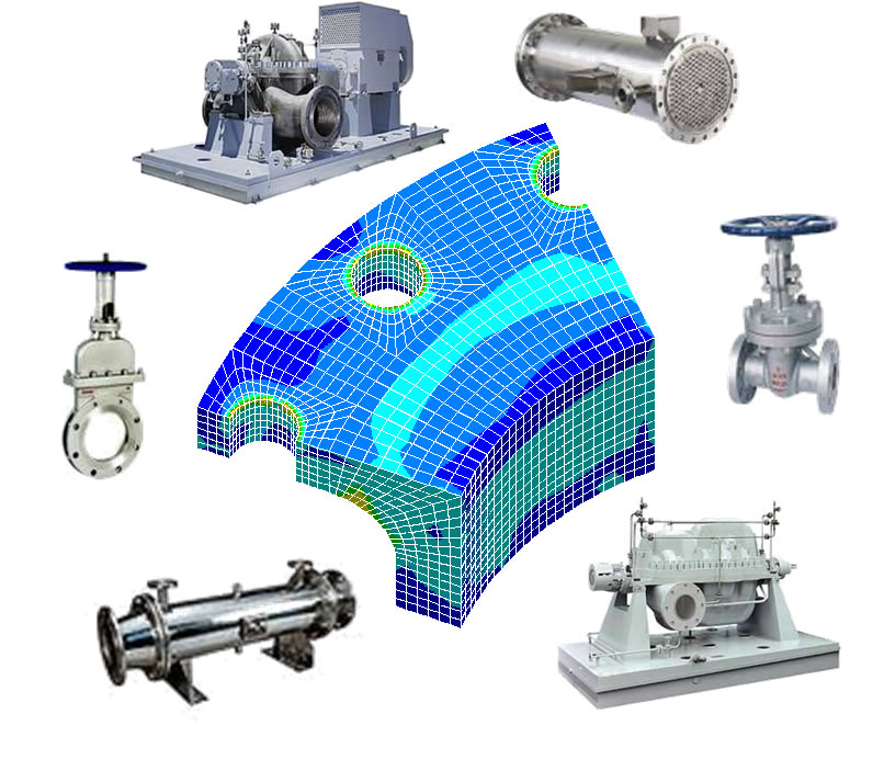
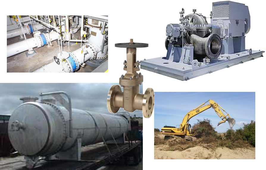
Product Selection
Forces Acting on Sealing Devices
Before we can properly select a sealing device, it’s important to understand the forces acting on the sealing device in the application. First, we will look at the forces in a flange assembly where a gasket is used.
Forces Acting on a Gasket
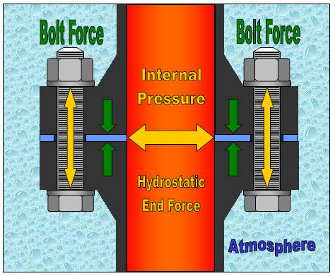
In a flange assembly, the gasket is placed between two flanges, which are then clamped together with bolts, studs, or other clamping devices.
In this example, the bolts are creating a clamping load, or bolt force, which compresses the gasket.
Once the media is introduced in the system, the internal pressure that is generated will try to push the gasket and separate the flanges. This force is called hydrostatic end force. If the hydrostatic end force exceeds the bolt force, the flanges will separate, and the gasket will leak or blow out.
The last external force we have to consider is the atmosphere. In other words, what’s going on outside the flange assembly?

Product Selection Criteria (STAMPS)
Bolts & Fasteners
 The most common method to clamp sealing devices in place is by using fasteners or bolts. There are multiple variables in a fastener that must be identified and understood in order to ensure that the sealing device receives proper loading.
First, we need to determine if the bolt or fastener threads are fine or coarse threads. Coarse threads, which are by far the most common in industry, are stronger, but not as efficient as fine threads. Therefore, a fine thread bolt requires less torque to generate the same load as a coarse thread bolt.
Secondly, flat washers can greatly improve load translation into the sealing device by creating a bearing-like surface for the nut or bolt head to slide on. Without washers, it is more likely that the nut or bolt head will bind against the contact surface of the flange, valve, or other equipment.
The third variable to consider is thread coating. Coatings are typically applied to improve fastener corrosion resistance. In addition, they can improve efficiency, thus resulting in higher compressive loads at a given torque.
The fourth variable to consider is thread lubricant. A non-lubricated bolt has less than 50% of the efficiency of a lubricated bolt. What that means is if you torque a non-lubricated bolt to 60 ft. lbs., the compressive load it generates will be approximately half of the load you would generate with the same bolt when lubricated. This concept will be demonstrated in the next few sections.
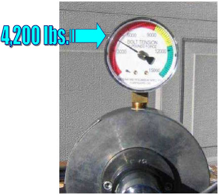
Bolt Force – Bolt #1 – No Lubricant
The device shown is a bolt tension device that is designed to measure load generated in pounds (lbs) when a given torque value is applied. In this example, a 5/8” SAE Grade 5 coarse thread carbon steel bolt has been installed and torqued to 60 ft. lbs. The resulting stress that is generated is 4200lbs.
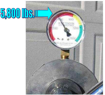
Bolt Force – Bolt #2 – Zinc-Plated, No Lubricant
In this example, we are now using the same size and grade, but this is a zinc-plated bolt. As you can see, in this case, the coating improves the efficiency of the bolt and the load generated. When the same torque of 60 ft. lbs. is applied, the compressive force generated increases to 5800lbs.; nearly a 30% increase in available compressive force.
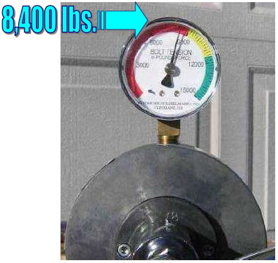
Bolt Force – Bolt #3 – Zinc-plated with Lubricant
The last example is the same size and grade zinc-plated bolt, but with thread lubricant (nickel-based Never Seiz). The compressive load generated with the same initial torque of 60 ft. lbs. is now 8400lbs! That is twice the force generated by the original carbon steel bolt, thus proving the importance of properly lubricating bolts.
Bolt Grade
This chart shows the more common fastener grades used in industrial applications, as well as their yield strengths, which is the stress point at which a bolt becomes permanently deformed (In other words, it will not spring back to its original size when the load is removed).
Bolt grade identification is extremely important when determining proper torque values for an assembly.
For example, ASTM A193 B8 stainless steel bolts are commonly used for chemical services where corrosion resistance is required. Here, there are two different B8 bolt designations shown, however, there is a significant difference in yield strength between a class 1 (most commonly used stainless steel bolt in chemical service) and a class 2 (strain-hardened stainless steel).
Notice the only difference in how these bolts are marked is a single line under the “B8” marking, thus emphasizing the importance of properly reading the markings.
For a more comprehensive list of bolt grades, contact Garlock Applications Engineering.

Media

Media is the fluid the sealing device is sealing in or out of an assembly.
Sealing devices are typically used to seal gases and/or liquids. Occasionally, a sealing device may be required to contain media in a solid form, however, many of these applications are in slurry form (a liquid and solid mixture). When choosing a product to seal a particular media, it is important to consider not only chemical compatibility but also emissions compliance.
For example, a sealing device that works very well for sealing liquids may be chemically compatible with certain gases but may not provide the necessary level of permeation resistance.
When dealing with refining applications, the two most common hydrocarbons encountered are the aliphatic and aromatic. Aromatic hydrocarbons, such as toluene, benzene, and xylene, are more chemically aggressive than aliphatic hydrocarbons, such as petroleum oil, kerosene, and diesel fuel. Therefore, aromatic hydrocarbons usually require more chemically-resistant sealing devices made from PTFE, graphite, or metal, where aliphatic hydrocarbons can be sealed with sealing devices constructed from fiber (I.E. aramid) and elastomers (nitrile or fluoroelastomers).
When dealing with strong oxidizers, alkalines, and acids, it is very important to understand the chemicals involved and their concentrations.

pH Scale
The pH scale is used to measure the hydrogen concentration of a chemical. As you can see from the chart shown, common household products that are used every day can, at the right concentration, have a similar pH rating to hazardous chemicals used throughout industry.
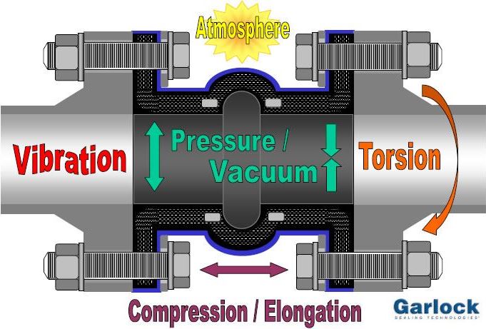
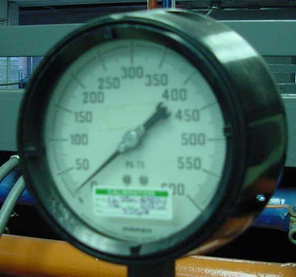
Pressure
 Most systems operate at some sort of “constant” pressure, however, if system upsets occur, it is important to factor that into the selection process, as well as make operational corrections to try to prevent those upsets from occurring. Here are a few examples of system pressure upsets:
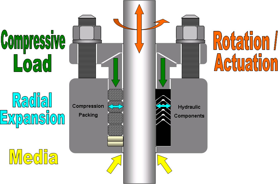
Speed

The last portion of STAMPS is the Speed.
Speed information is required for compression packing and hydraulic components used in pumps and other rotating or reciprocating equipment.
In the case of rotating equipment, the speed must be expressed in feet per minute (FPM). The reason speed is expressed this way is that a large-diameter shaft rotating at a given number of revolutions per minute (RPM) will actually have a higher FPM surface speed than a small-diameter shaft rotating at the same RPM.
In reciprocating applications, it is important to know the length of the stroke and cycles per minute. This information will then be used to calculate the speed of the shaft or piston.